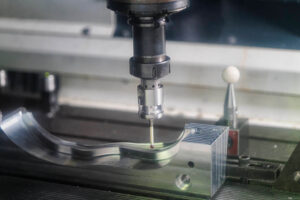
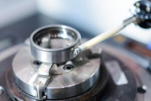
If you are a professional practitioner in the machinery industry, it is not difficult to understand the size, structure and various professional symbols on the drawings of precision metal parts processing, but if you are initially in contact with the CNC processing industry, the dazzling drawings It may give you a big headache, especially the processing structure and basic structure of parts. If you don’t understand these contents, it will be difficult to guarantee the efficiency and effect of many things. Therefore, we have compiled this article to help you understand various parts Processing mechanism and common parts structure.
Machining structures on parts
Undercut and wheel overrun
When cutting parts, in order to facilitate the withdrawal of the tool and ensure that the contact surfaces of related parts are close during assembly, the step of the machined surface should be pre-machined with an undercut groove or a grinding wheel overrun groove.
The size of the undercut groove when turning the outer circle can generally be marked in the form of “groove width × diameter” or “groove width × groove depth”. Grinding wheel overtravel groove when grinding outer circle or grinding outer circle and end face.
Drilling structure
The blind hole drilled with a drill bit has a cone angle of 120° at the bottom, and the drilling depth refers to the depth of the cylindrical part, excluding the cone pit. At the transition of the stepped drill hole, there is also a circular platform with a cone angle of 120°, and its drawing method and dimensioning method.
When drilling with a drill bit, the axis of the drill bit is required to be as perpendicular as possible to the end face of the drilled hole to ensure accurate drilling and avoid the drill bit from breaking. The correct configuration of the three borehole faces.
Bosses and Dimples
The contact surface of the part with other parts is generally processed. In order to reduce the processing area and ensure good contact between the surfaces of the parts, bosses and pits are often designed on the casting. Bolted support surface bosses or support surface pits; in order to reduce the processing area, it is made into a groove structure.
Common Part Structure
Shaft parts
Such parts generally include shafts, bushings and other parts. When expressing the view, as long as a basic view is drawn and appropriate cross-sectional views and dimensions are marked, the main shape features and local structures can be expressed. In order to facilitate the viewing of drawings during processing, the axis is generally placed horizontally for projection, and it is best to choose a position where the axis is a side vertical line.
When marking the size of shaft sleeve parts, its axis is often used as the radial dimension reference. In this way, the design requirements and the process benchmarks during processing (when the shaft parts are processed on the lathe, the center hole of the shaft is supported by thimbles at both ends). The benchmark in the length direction often chooses important end faces, contact surfaces (shaft shoulders) or processing surfaces.
Cover parts
The basic shape of this kind of parts is a flat disc, generally including end covers, valve covers, gears and other parts. Their main structure generally has a rotating body, usually with various shapes of flanges and uniformly distributed round holes. and local structures such as ribs. When selecting the view, generally choose the sectional view through the symmetry plane or the axis of rotation as the main view, and add appropriate other views (such as left view, right view or top view) to express the shape and uniform structure of the part.
When marking the size of disc cover parts, the axis passing through the shaft hole is usually selected as the radial dimension reference, and the main dimension reference in the length direction is often selected from the important end face.
Fork parts
Such parts generally include shift forks, connecting rods, supports and other parts. Because their processing positions are changeable, when selecting the main view, the working position and shape features are mainly considered. For the selection of other views, two or more basic views are often required, and appropriate partial views, cross-sectional views, etc. are also used to express the local structure of the part. The view selection shown in the stepping seat part drawing is concise and clear. For expressing the width of the bearing and the rib, the right view is not necessary, but for the T-shaped rib, it is more appropriate to use the section.
When marking the size of fork-like parts, the installation base surface or the symmetrical plane of the part is usually selected as the size reference.
Box parts
Generally speaking, the shape and structure of this type of parts are more complex than the previous three types of parts, and the processing position changes more. Such parts generally include valve body, pump body, reducer box and other parts. When selecting the main view, the main consideration is the working position and shape features. When choosing other views, various auxiliary views such as cross-section, section, partial view and oblique view should be used according to the actual situation to clearly express the internal and external structure of the part.
In terms of dimensioning, the axis required by the design, the important installation surface, the contact surface (or processing surface), and the symmetry plane (width, length) of some main structures of the box are usually selected as the size benchmark. For the part of the box that needs to be cut, the size should be marked as far as possible according to the requirements for processing and inspection.
Hope the above content is helpful to you.


